- Joined
- Sep 9, 2012
- Messages
- 784
- Location
- Wiedemar, Germany
- First name
- Joachim
Machinery:
Zetor 2011, Zetor 3045, Zetor 5011, Zetor 7340 Economic
Installation instructions for cylinder head, piston, connecting rod and crankshaft Zetor UR1 Zetor 2011-7341:
The installation position of the head gasket can be checked using the metal ring, the wider side of the ring and, if applicable, the label should face upwards, the narrower side downwards!
All information is based on information from original Zetor documents such as the workshop manuals or is taken from good professional practice.
However, despite thorough research, no guarantee can be given!
- Balancing weights
- Check balancing weights/counterweights of the crankshaft for firm, straight seating, the tightening torque is 35 - 40 Nm directly on the SW 14 screw or approx. 32 Nm on the approx. 80 mm long "Adapter wrench of the balancing weight"
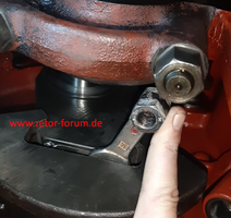
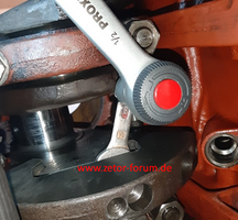
according to the construction template (see photos, link follows), the screws are tightened with a new Locking plate and preferably additionally with Loctite "screw tightening agent".
More information (German, but you can use translator):
- Check balancing weights/counterweights of the crankshaft for firm, straight seating, the tightening torque is 35 - 40 Nm directly on the SW 14 screw or approx. 32 Nm on the approx. 80 mm long "Adapter wrench of the balancing weight"
- Linear liners
- The seat of the liner collar in the engine block and the sealing surface of the sealing rings of the liner in the engine block must be absolutely clean before assembly.
- Before assembling the liners, the sealing rings and the sealing surface of the sealing rings must be well oiled to avoid damage to the sealing rings during assembly. Insert the liners evenly by hand or with light blows from a rubber hammer.
- After assembly, measure the cylinder liner projection to ensure that the cylinder liners extend far enough beyond the top edge of the engine block so that the seal using the head gasket still works. It should be between a minimum of 0.03 and a maximum of 0.07 mm.
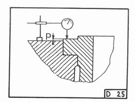
- Pistons, piston rings and piston pins
- Use pistons of the same design, weight and size as the cylinder liner (A, B or C), this is usually engraved on the piston and the cylinder liner.
- The piston, without piston rings, must be heated to 90°C for assembly of the piston pin, the piston pin should be cooled.
- Insert the circlips of the piston pins so that their opening faces upwards or downwards, but not to the side.
- The permissible joint clearance of the piston rings is 0.35 to max. 0.55 mm, measured at the joint with the piston ring inserted into the cylinder liner approx. 2 cm from the top.
- Connecting rods
- Weighing and adjusting connecting rods
The maximum permissible deviation in the weight of the complete connecting rods of an engine is:
max. 10 g - less is of course optimal (up to max. 5 g).
Background information:
A weight difference of 10 g in the lower part of the connecting rod, with a radius of r=55 mm and a speed of 2200 rpm, leads to a centrifugal force/unbalance of 14 N, which corresponds to about 1.5 kg.
The lower part of the connecting rod participates in a rotary movement together with the connecting rod bearing shell.
The upper part (piston side) performs an oscillating movement together with the piston.
It is therefore optimal to balance the connecting rods by weighing and adjusting them on both sides and thus not only adjust the total weight of the connecting rods to each other, but also adjust the upper and lower parts of the connecting rods separately in the same weight ratio.
In this way, harmful forces caused by different connecting rod weights can be minimized.
Some say it is unnecessary, but we all know how an unbalanced wheel on a car behaves, and it is only a matter of a few grams. A wheel on a car rotates at 100 km/h at around 1000 rpm.
All connecting rods are weighed individually, lying horizontally, once on the connecting rod bearing side and once on the head side.
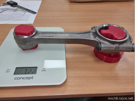
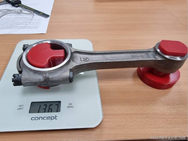
Source: rosch8.rajce.net
The values must be noted and then adjusted to the smallest values.
If this is larger, all connecting rods of a weight class must be installed or, if necessary, the weight of the connecting rod that is too heavy must be reduced at the possible points:
- Connecting rod WITHOUT hammer head (older)': at the bottom of the connecting rod bearing shell and at the top on the side.
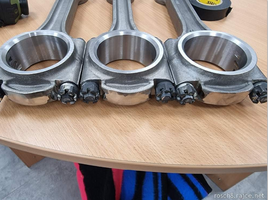
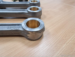
- Connecting rod WITH hammer head:
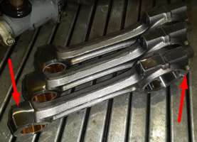
- The expansion bolts and the nuts of the connecting rod bearings must always only be used once and then replaced. The tightening torque in the UR1 is usually 80-90 Nm with oil-moist threads.
There is the older design with castle nuts+spling and the newer one with normal nuts. - Installation position of the connecting rods in the engine
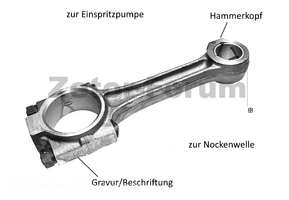
- Connecting rod with hammer head
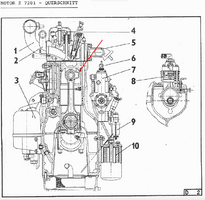
Design commonly used in newer UR1 Zetors, these must be installed with the hammer head pointing towards the injection pump.
- Connecting rod WITHOUT hammer head:
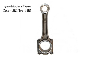
In older models of the UR1 this hammer head was not yet available, here the connecting rods were symmetrical, but in these cases the engraving/labeling on the connecting rod is usually installed facing the camshaft.
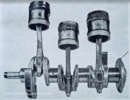
The possible reason for this is the Y-shaped lubrication groove in the piston pin bearing bush.
This means that the connecting rods must be installed in such a way that the V-shaped end of the Y-lubrication groove is installed facing the injection pump.
- Connecting rod with hammer head
- Weighing and adjusting connecting rods
- Head gasket
- To select the head gasket, measure the oversize of each piston in the top dead center position of the piston and approx. 1 cm from the piston edge in relation to the seat surface of the engine block (dial gauge):
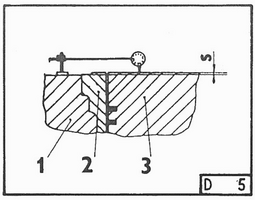
1 - engine block, 2 - cylinder liner, 3 - piston, S - oversize
If the measured value "S" on a piston is:
Engine type Z 7701(Zetor 7711, 7745)- 0.00 - 0.50 mm, a 1.2 mm head gasket must be installed
- 0.50 - 0.80 mm, a 1.5 mm head gasket to be fitted
- To select the head gasket, measure the oversize of each piston in the top dead center position of the piston and approx. 1 cm from the piston edge in relation to the seat surface of the engine block (dial gauge):
Engine type Z 6901, Z 7001, Z 7201 (Zetor 4911 to 7245)
- 0.00 - 0.35 mm, a 1.2 mm head gasket must be fitted
- 0.35 - 0.80 mm, a 1.5 mm head gasket must be fitted
Measure each piston and select the appropriate cylinder head gasket for each piston.
TURBO engines generally have the 1.5mm turbo head gasket!
From my own experience, I would also apply and recommend the recommendations for the Z 6901 to Z 7201 engines for the engines from Zetor 2011 onwards.
The installation position of the head gasket can be checked using the metal ring, the wider side of the ring and, if applicable, the label should face upwards, the narrower side downwards!
- Tightening torques for the cylinder head bolts see "Tightening torques" or the Zetor workshop manual , tighten bolts crosswise when the engine is cold. Retightening is not necessary, cylinder head bolts can be used multiple times.
- Adjusting the valve clearance see "Valves - Checking and adjusting the valve clearance"
All information is based on information from original Zetor documents such as the workshop manuals or is taken from good professional practice.
However, despite thorough research, no guarantee can be given!
