- Joined
- Sep 9, 2012
- Messages
- 410
- Location
- Germany, Wiedemar
- First name
- Joachim
Machinery:
Zetor 2011, Zetor 3045, Zetor 5011, Zetor 7340 Economic
[centered]Injectors[/centered]
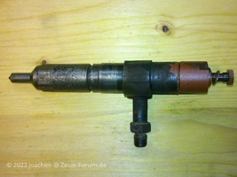
Complete nozzle assembly with injection valve:
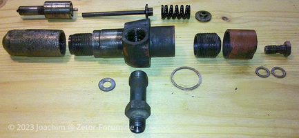
Disassembled nozzle assembly:
Troubleshooting if an injector is suspected to be the source of the problem:
Part assignment using the example of the injection valve series "0" and "2"
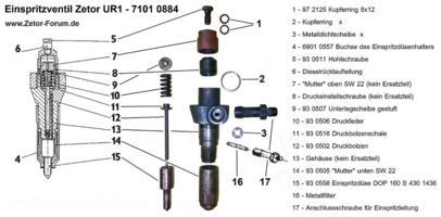
The designation applied to the actual injection nozzle is as follows:
Example: DOP 160S 430-1436 (Zetor 5011 or 5211 e.g.)
D = nozzle
O = hole
P = expanded
160 = nozzle beam angle
S = size range of the nozzle (e.g. P, S, T, U, V)
4 = number of holes
30 = diameter of the holes (here 0.30 mm)
1436 = Nozzle design version
Here is a photo of the metal filter (picture no. 16 above) in the pipe socket:
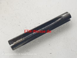
This can be removed and cleaned if necessary.
Installation instructions for installing the nozzle in the nozzle assembly and inserting the nozzle assembly into the cylinder head on UR1 engines:
For the UR1 models (2011-7340 Turbo), make sure that the lines on the nozzle itself and the nozzle body are congruent. Otherwise, the nozzle insert must be loosened, twisted and secured again so that the lines are congruent.
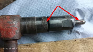
It is also important to insert the nozzle holder into the cylinder head in such a way that the connecting piece on the nozzle holder 1-1.5 mm is away from the left (front) stud bolt of the nozzle holder holder and to close it tightly is to pull. So neither directly adjacent nor more than 1.5 mm away!
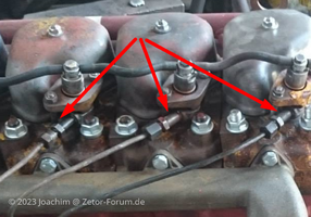
If the nozzle seat and/or nozzle assembly cone is no longer as good as new, it makes sense to place an extremely thin aluminum sealing washer under it to ensure the tightness of the combustion chamber at this point. In any case, both sealing surfaces must be cleaned and freed of rust, paint or dirt before reassembly.
Such sealing washers can be obtained, for example, from the Weisse spare parts dealer (ETH-Weisse.de).
Important!
If the gap is too large and/or the lines are not congruent, the injection nozzle, which sits at an angle in the cylinder head in the nozzle assembly, will not spray exactly towards the center of the combustion chamber as required, but possibly onto the inner wall of the combustion chamber liner. This can lead to poor engine running (smoking, poor performance) or even damage to the pistons and liners.
Complete nozzle assembly with injection valve:

Disassembled nozzle assembly:

Troubleshooting if an injector is suspected to be the source of the problem:
With the engine running, loosen the union nuts of the nozzle lines one by one by half a turn and then tighten them again. Normally, the engine performance drops audibly. If it does not do this for a cylinder, then the cylinder with the suspected defect has been found.
This is easier to determine with 1-3 cylinder engines than with 6-cylinder engines. Motors.
Then remove the nozzle line from the cylinder in question, namely at the nozzle and at the injection pump, never install injection lines of different lengths and cleanliness is the top priority here!
The steel pipes can only be bent a few millimeters to one centimeter to the side, as the highly stressed material can quickly be damaged by the resulting compression and could then break at these points later during operation.
Repeated loosening and tightening of the connections can also damage the cones of the diesel pipes, so proceed carefully.
Any existing cable bridges must be dismantled beforehand.
Dismantle leakage oil lines and use new copper seals when reassembling.
The nozzle assembly can now be completely dismantled.
Part assignment using the example of the injection valve series "0" and "2"

The designation applied to the actual injection nozzle is as follows:
Example: DOP 160S 430-1436 (Zetor 5011 or 5211 e.g.)
D = nozzle
O = hole
P = expanded
160 = nozzle beam angle
S = size range of the nozzle (e.g. P, S, T, U, V)
4 = number of holes
30 = diameter of the holes (here 0.30 mm)
1436 = Nozzle design version
Here is a photo of the metal filter (picture no. 16 above) in the pipe socket:

This can be removed and cleaned if necessary.
Installation instructions for installing the nozzle in the nozzle assembly and inserting the nozzle assembly into the cylinder head on UR1 engines:
For the UR1 models (2011-7340 Turbo), make sure that the lines on the nozzle itself and the nozzle body are congruent. Otherwise, the nozzle insert must be loosened, twisted and secured again so that the lines are congruent.

It is also important to insert the nozzle holder into the cylinder head in such a way that the connecting piece on the nozzle holder 1-1.5 mm is away from the left (front) stud bolt of the nozzle holder holder and to close it tightly is to pull. So neither directly adjacent nor more than 1.5 mm away!

If the nozzle seat and/or nozzle assembly cone is no longer as good as new, it makes sense to place an extremely thin aluminum sealing washer under it to ensure the tightness of the combustion chamber at this point. In any case, both sealing surfaces must be cleaned and freed of rust, paint or dirt before reassembly.
Such sealing washers can be obtained, for example, from the Weisse spare parts dealer (ETH-Weisse.de).
Important!
If the gap is too large and/or the lines are not congruent, the injection nozzle, which sits at an angle in the cylinder head in the nozzle assembly, will not spray exactly towards the center of the combustion chamber as required, but possibly onto the inner wall of the combustion chamber liner. This can lead to poor engine running (smoking, poor performance) or even damage to the pistons and liners.


